Introduction
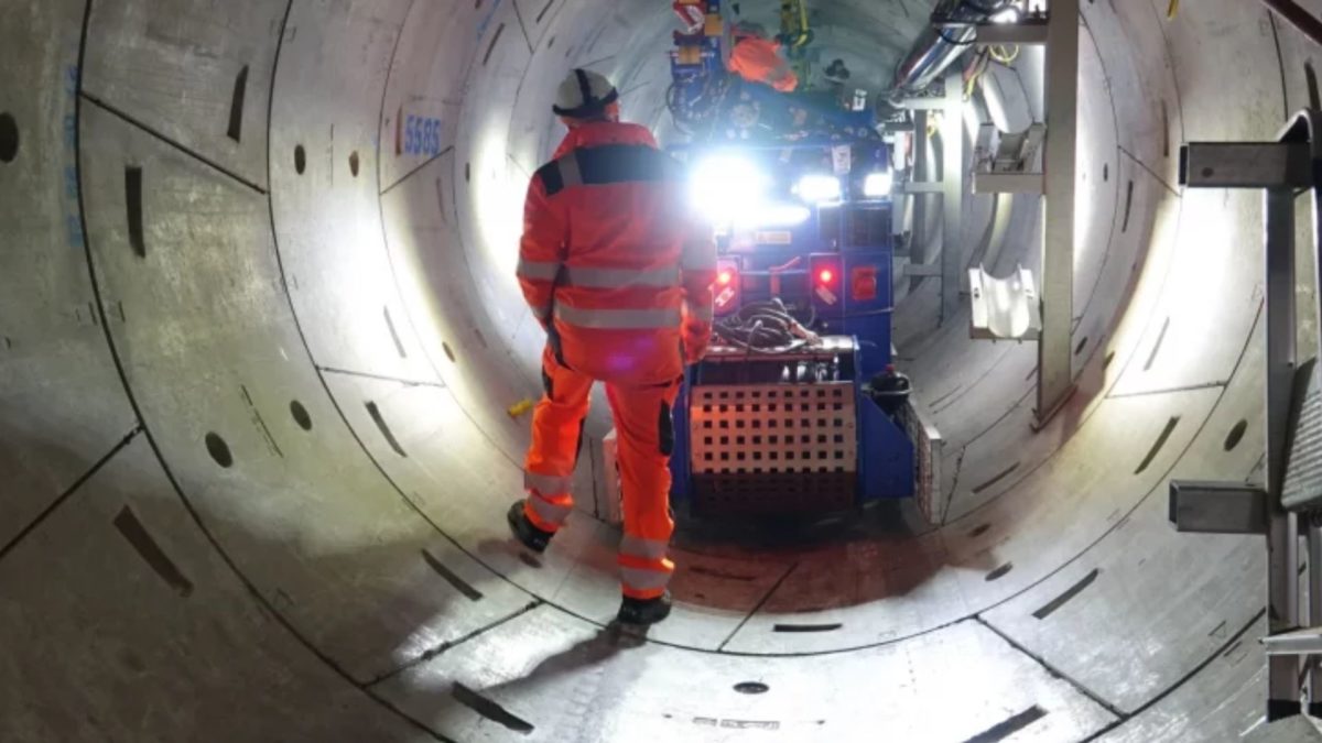
As an industry leader in designing and manufacturing custom winches, Rotrex recently took on a challenging task: creating two bespoke hydraulic-powered winches for the high-profile London Power Tunnels project. Collaborating with G.O.S. Tool & Engineering Services and Balfour Beatty, Rotrex actively delivered a solution that showcased their design expertise and met the project’s unique requirements.
Project Background
G.O.S. Tool & Engineering Services turned to Rotrex when they needed two custom designed hydraulic powered winches to pull high voltage power cables in the London Power Tunnels. Older power cables are typically situated under the streets of London and replacing this aging infrastructure causes massive amounts of disruption to traffic.
The National Grid initiated the London Power Tunnels project to reinforce the UK capital’s power infrastructure with over 60km of tunnels carrying high voltage cables. Designed to house a number of 40kvA cables, installed in 1200m lengths, each valued at £300,000, these 3-meter diameter tunnels required custom winches to seamlessly integrate with the Automated Cable Installation Equipment (ACIE) developed by G.O.S. Tool & Engineering Services for Balfour Beatty.
Client Requirements
The project’s unique challenges necessitated specific winch design requirements:
- Hydraulic operation with 350 bars of pressure with a 1/2inch hose and a 6l/min maximum flow rate.
- Must have a useable 250m of 10mm diameter Dyneema rope, capable of pulling 2 tons.
- A rotational speed of 10m/min.
- Maximum width of 900mm to fit the confined tunnel space and ACIE.
- Compatibility with ACIE while remaining demountable and liftable.
- Integration with an external control system for managing speed and force.
- Operational resilience in temperature extremes from -25°C to 40°C, and resistance to wind and water ingress.
Innovative Design Solutions
Rotrex’s Project Engineer actively tackled these constraints with creative solutions:
- Integrated the motor and gearbox within the drum to minimize width.
- Designed a grooved drum with a pitch of 10-15% of the finished rope diameter, resulting in an 11-12mm pitch.
- Installed a CAN encoder to measure rotational speed and distance pulled, without exceeding the width limit.
- Centrally mounted drum with labelled lifting points.
- Tested to 2.5 tons of dead weight and brake slip tested to 150%
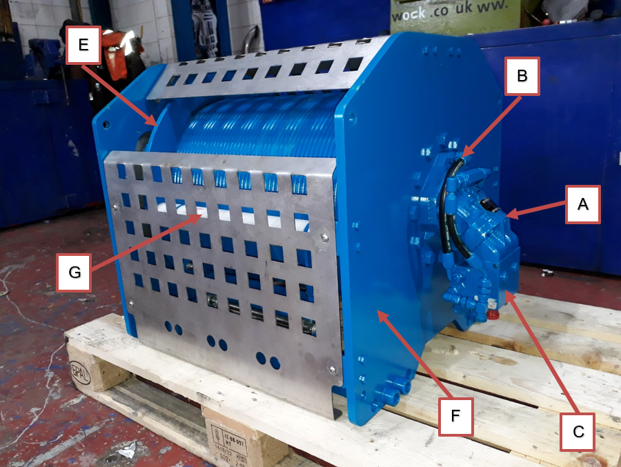
A – Hydraulic Motor – The part delivering the torque to drive the winch drum.
B – Gearbox & Brake – Automatic spring applied brake that stops the winch running away when power is removed from the motor.
C – Manifold – Fitted between incoming hydraulic pipes and the motor to provide for the over centre valves that provide a hydraulic motor lock.
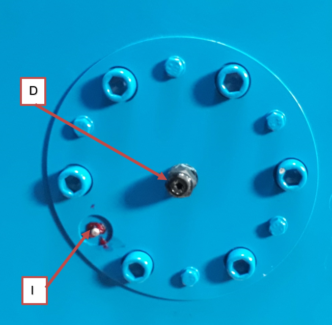
D – Encoder – Fitted on the opposite side of the drum to the motor, the encoder counts drum rotations so that the control system knows where the winch is operating.
E – Drum – The drum winds and stores the rope. The rope is fitted to the drum using a rope clamp. The drum is machined with a spiral to aid rope scrolling.
F – Winch Frame – The frame supports the drum and other winch parts.
G – Press Roller – Prevents the rope from “birds nesting” in slack rope conditions.
H – Rope – Facilitates the transmission of the load to the winch drum.
I – Grease point – End bearing grease point.
Conclusion
By addressing the unique challenges of the London Power Tunnels project, Rotrex demonstrated its ability to actively design and manufacture bespoke winches for complex projects. This successful collaboration with G.O.S. Tool & Engineering Services and Balfour Beatty not only showcased Rotrex’s design expertise but also reinforced the company’s position as the go-to partner for custom winch solutions.